
Surge Protection Solutions
For over 130 years, Mersen has been a leader in the electrical power industry. Since entering the surge protection market in 1996, we’ve become a trusted player, revolutionizing the industry with the development of the Thermally Protected MOV (TPMOV®), leading to its widespread adoption.
-
Why Surge Protection?
What is a surge?
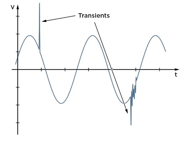
Surge, or transient voltage, is a brief overvoltage spike or disturbance on a power waveform that can damage, degrade, or destroy electronic equipment within any home, commercial building, industrial, or manufacturing facility. Transients or surges can reach amplitudes of tens of thousands of volts, with a duration of less than a half-cycle of the normal voltage waveform.
Every piece of electrical equipment is designed to operate at a specified nominal voltage such as 120 Vac, 240 Vac, 480 Vac, and so on. Most equipment is designed to handle minor variations in their standard nominal operating voltage however, surges can be very damaging to nearly all equipment.
-
Why Surge Protection?
What causes surges?
A common source for surges generated inside a building are devices that switch power on and off. This can be anything from a simple thermostat switch operating a heating element to a switch-mode power supply found on many devices. Surges that originate from outside the facility include those due to lightning and utility grid switching.
Internal sources of surges come from equipment and switching, including:
- Switching of Electrical Loads
- Contactor, relay and breaker operations
- Switching of capacitor banks and loads (such as power factor correction)
- Discharge of inductive devices (motors, transformers, etc.)
- Starting and stopping of loads
- Fault or arc initiation
- Arcing (ground) faults
- Fault clearing or interruption
- Power system recovery (from outage)
- Loose connections
- Magnetic and Inductive coupling
- Elevators, heating ventilation and air conditioning systems (HVAC with variable frequency drives), and fluorescent light ballasts, copy machines, and computers
External sources of surges
The most recognizable source of surges generated outside the facility is lightning. Although lightning can be somewhat infrequent in certain regions, the damage it can cause to a facility can be catastrophic.
Other external sources of surges include utility-initiated grid and capacitor bank switching. During the operation of the electrical grid, the utility may need to switch the supply of power to another source or temporarily interrupt the flow of power to its customers to aid in clearing a fault from the system. This is often the case in the event of fallen tree limb or small animal causing a fault on the line. These interruptions of power cause surges when the power is disconnected and then reconnected to the customer loads.
Electric utilities produce electricity from a number of power-generation facilities, as utilities switch the supply of power from one grid to another, power disturbances occur, including transients or spikes, and under- and over-voltage conditions.
-
Why Surge Protection?
Why do I need surge protection?
Damages due to electrical surges is one of the leading causes of failure of electrical equipment and it is estimated that damage due to lightning alone costs the US economy $5‐6 billion dollars per year according to the National Lightning Safety Institute. Residences in the US suffered damage to the tune of $825 million according to the Insurance Information Institute in 2016 alone. This number has risen 40% since 2007 due to increase of electronics and electrical equipment susceptible to surge.
The cost of an average downtime for a critical facility due to surge damage is $130,000 per event. On average a typical building experiences surge up to 150 times a month. America’s dependence on connected devices and smart electronics establishes a need to protect the safe and reliable operation of such equipment that is susceptible to electrical surge damage.
Surge protection is a cost-effective solution to prevent downtime, improve system and data reliability, and elimination of equipment damage due to transients and surges for both power and signal lines. It is suitable for any facility or load (1000 volts and below).
-
Why Surge Protection?
How does an SPD work?
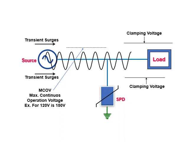
A Surge Protective Device - SPD - works like a pressure relief valve in a water system… it is normally installed in parallel with the equipment it’s protecting, connected to ground. Under normal circumstances, at nominal voltage, an SPD will be quietly on guard ready to protect your system. During a surge condition, the SPD becomes a conductor, and drives the potentially damaging transient voltage to ground, protecting your equipment. A properly specified and installed SPD will protect your equipment from many surges over many years- the device is not consumable- once the surge has passed, the SPD will go back to it’s normal status, not conducting (open circuit to ground) and guarding against future surges.
There are different technologies that can be used for surge protection; Mersen Surge Trap® utilizes Metal Oxide Varistor (MOV) combined with thermal protection for a combination of fast performance and safety.
-
Technology and Advantages
Technology
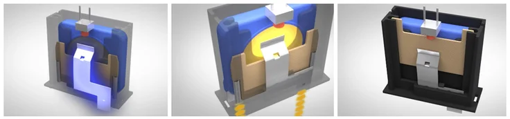
Mersen Surge-Trap® SPDs product line feature our Thermally Protected MOV (TPMOV) technology, a fail-safe, and most reliable surge protection solution on the market.
Mersen’s patented invention TPMOV technology, eliminates common and possibly catastrophically failure when the MOV reaches end of life.
Internally the TPMOV is comprised of a voltage clamping device and a disconnecting apparatus that monitors the status of the metal oxide disk, making the TPMOV a fail-safe device. In the event of an overvoltage breakdown, the metal oxide disc is securely disconnected from the system power by an arc shield.
Upon failure, the TPMOV is also equipped with a visual pin indicator as well as a normally open micro-switch, providing remote indication if applicable.
-
Technology and Advantages
TPMOV
-
Technology and Advantages
Mersen TPMOV Technology
-
Technology and Advantages
Advantages
- Thermally Protected MOV (TPMOV) Technology: Using our protection expertise and convinced that technological innovation is essential, Mersen developed the safest surge protection technology. TPMOV eliminates MOV’s hazardous and destructive failure modes (thermal runaway).
- High Short-Circuit Current Rating: Feature high SCCR rating to ensure that Mersen’s TPMOV/SPDs can be installed in almost any location- regardless of available fault current (AFC)- and safely disconnect from the system when necessary.
- Surge Protection Solution for Any Application: We offer different types of mounting option; Panel Mounted – Hard wired, Din Rail SPDs, Surface Mounted, OEM Components, and a big range of voltage configurations ensures the best solution for any application for any application.
- Power distribution systems including service entrance and distribution panels, control cabinets, programmable logic controllers, electronic motor controllers, equipment monitoring, lighting circuits, metering, medical equipment, critical loads, back-up power, UPS, HVAC equipment, data centers, renewable energy such as solar and wind power, among others.
- Industrial automation signaling, cable TV, security systems, alarm signaling, telecommunication and computer networks.
- High Quality: Our products are compliant with the latest ANSI/UL 1449 standards. Mersen’s TPMOV/SPDs are 100% electrically inspected and tested.
- Status Indication & Advanced Options: A wide range of options, including status indicators, remote monitoring and EMI/RFI noise filtering, offers a durable and most reliable surge protection solution.
- Thermally Protected MOV (TPMOV) Technology: Using our protection expertise and convinced that technological innovation is essential, Mersen developed the safest surge protection technology. TPMOV eliminates MOV’s hazardous and destructive failure modes (thermal runaway).
-
Application Guide
Where do I apply surge protection?
All electrical equipment is vulnerable to electrical surges. Typical SPD applications within industrial, commercial, and residential include:
- Power distribution, control cabinets, programmable logic controllers, electronic motor controllers, equipment monitoring, lighting circuits, metering, medical equipment, critical loads, back-up power, UPS, HVAC equipment
- Communication circuits, telephone or facsimile lines, cable TV feeds, security systems, alarm signaling circuits, entertainment center or stereo equipment, kitchen or household appliances
Location and Amount of Protection
- Categories ("Surge-Trap and the Different kA Ratings" and "UL 1449 4th Edition Location and/or Type Designation")
- System Voltage and Configurations: How much protection does my facility need?
Device Types and Performance Parameters- Voltage protection, clamping voltage, VPR rating- most important/critical to protecting equipment ("Surge Protective Device Performance and Cascaded Protection").
- Inominal Rating
- Imax Rating- Capacity (leads to warranty and life of SPD)
-
Application Guide
Where do I need to install surge protection?
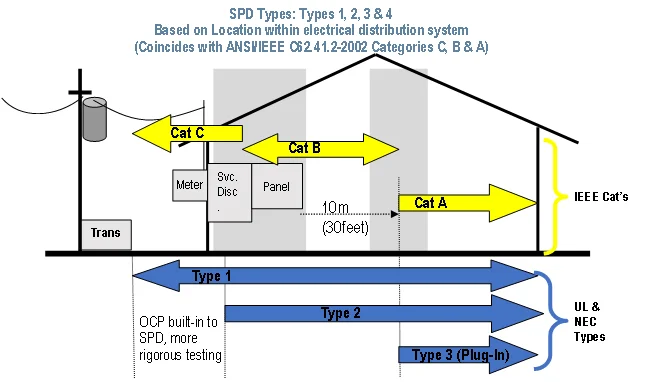
IEEE C62.41.1 defines location categories. These reflect the location in the power system and roughly correspond to UL device types. The Location categories are as follows:
- Location Category C – Outside, service entrance and equipment (Voltage Peak Value 6-10kV)
- Location Category B – Service Equipment, major feeders, and short branch circuits (Voltage Peak Value 3-6kV)
- Location Category A – Long branch circuits and receptacles (Voltage Peak Value 0.5-6kV)
Examples of the locations are as follows:
-
Application Guide
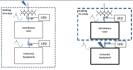
Locations outside building
Note that electrical equipment located outside of the building envelope should be considered Category C and Type 1 devices should be utilized at the circuit (more on the device type topic below). The reason is that this equipment is more susceptible to external surge events which can bypass the service SPD and enter the building through the external equipment and wiring. See below for example.
-
Application Guide
UL Standard 1449
UL Standard 1449 defines several different types of devices based upon their installation location and use. The three most common are described as follows.
- Type 1 – Permanently connected SPDs intended for installation between the secondary of the service transformer and the line side of the service equipment overcurrent device, as well asthe load side, including watt-hour meter socket enclosures and Molded Case SPDs intended tobe installed without an external overcurrent protective device.
- Type 2 – Permanently connected SPDs intended for installation on the load side of the service equipment overcurrent device; including SPDs located at the branch panel and Molded CaseSPDs.
- Type 3 – Point of utilization SPDs, installed at a minimum conductor length of 10 meters (30 feet) from the electrical service panel to the point of utilization, for example cord connected,direct plug-in, receptacle type and SPDs installed at the utilization equipment being protected.See marking in 80.3. The distance (10 meters) is exclusive of conductors provided with or used to attach SPDs.
-
Application Guide
System Voltage and Configuration
Knowledge of the system voltage and configuration is critical in determining the correct device for the application. Each device has a maximum continuous operating voltage (MCOV). The MCOV must not be exceed in any of the potential operating conditions of the electrical system, or this could cause unnecessary failure of the device. Given that voltage regulation requirements in the United States allow for up to +/-6 percent of nominal (according to ANSI C84.1), a typical MCOV will be greater than 20 percent above the nominal line-ground voltage. The electrical system configuration is based on the secondary side of upstream transformer, not by how the load is connected. Most SPD mis-orders are misunderstandings related to grounding or neutrals. When a system is referred to as a grounded system, this means that the system is electrically referenced to ground, not that there is a safety ground. By convention, ground wires are not counted as one of the wires for SPDs (3-wire, 4-wire, etc.). Ungrounded and High-Resistance Grounded systems can cause issues with SPDs if they are not properly selected. This is due to the capability of these systems to hold a ground fault indefinitely which can result in raised potential to ground in un-faulted phases. See Mersen Tech Topic TT-SPN4 and Fact Sheet FS-Surge-Electrical-System-Guide for more information.
-
Application Guide
How Much Protection Does your Facility Requires?
The level of protection your facility requires involves different considerations, which are described in IEEE C62.41.2. When selecting the SPD surge capacity some considerations include:
- Protection desired depending upon the application. In applications such as data processing, critical medical processes, or manufacturing processes, any interruption or upset of a process is likely to be unacceptable thus a high protection level would be required.
- Equipment sensitivity to damage from surges. The sensitivities will be different for hardware failure or process upset.
- Value of equipment and downtime: How critical is the load and function of the load?
- Equipment sensitivities
- The power environment – surges
- The power environment – electrical system
- Performance of SPDs
- Protection
- Durability
- Failure mode
- The test environment, proper short-circuit currents
- Total and relative costs
- An electrical system should be fully protected by a system of SPDs, having your highest capacity SPD near the service entrance, and individual panels and pieces of equipment including their own dedicated surge protection as a secondary line of defense.
-
Application Guide
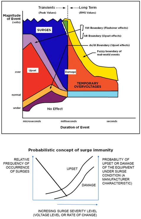
Equipment Susceptibility with the Surge Environment Level
The equipment susceptibility with the surge environment level involves the probabilistic intersection of two distributions:
-
Applications Guide
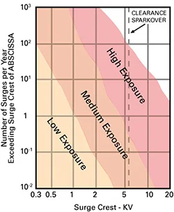
Exposure Levels
In Low-Voltage (1000 V and Less) AC Power Circuits, IEEE C62.41.2, Recommended Practice on Characterization of Surges describes location categories and exposure levels. Exposure Levels are qualitative:
- Low exposure: applications known for low lightning activity, little load switching
- Medium exposure: systems and geographical areas known for medium to high lightning activity or with significant switching transients or both
- High exposure: those rare installations that have greater surge exposure than those defined as low or medium
-
Codes and Standards
IEEE Codes and Standards
IEEE C62.41.1, “Guide on the Surge Environment in Low-Voltage (1000 V and less) AC Power Circuits”
This guide, the first in the trilogy, provides readers with comprehensive information on surges, the environment in which they occur and is a reference for the second document of the trilogy.IEEE C62.41.2, “Recommended Practice on characterization of Surges in Low-Voltage (1000 V and less) AC Power Circuits”
This guide, the second in the trilogy, presents recommendations on the selection of surge waveforms, amplitudes of surge voltages and currents used to evaluate equipment immunity and performance of SPDs. Two recommended “standard” waveforms are used as a simplified representation of the surge environment:IEEE C62.45, “Recommended Practice on Surge Testing for Equipment Connected to Low-Voltage (1000 V and Less) AC Power Circuits.”
This guide, the third in the trilogy, focuses on surge testing procedures (using simplified waveform representations) for obtaining reliable measurements and enhancing operator safety. The intent is to provide background that can help determine whether equipment or a circuit has adequate ‘withstand’ capability. Signal and data lines are not addressed in this document.The document does not indicate withstand levels that might be assigned to specific equipment. An important objective of the document is to call attention to the safety aspects of surge testing. Underwriters Laboratories, Inc. uses these guidelines as a reference in their performance and safety testing.
In addition, IEEE has produced the following standards for the application and testing of SPDs.
- C62.11 Standard for Metal-Oxide Surge Arresters for AC Power Circuits (>1 kV)
- C62.36 Standard Test Methods for Surge Protectors Used in Low-Voltage Data, Communications, and Signaling Circuits
- C62.41.3 Guide on Interactions between Power System Disturbances and Surge-Protective Devices
- C62.41.4 Recommended Practice on Surge Testing for Equipment Connected to Low-Voltage (1000V and Less) AC Power Circuits
- C62.42 Guide for the Application of Component Surge-Protective Devices for Use in Low-Voltage [Equal to Or Less Than 1000 V (ac) Or 1200 V (dc)] Circuits
- C62.43 Application of Surge Protectors Used in Low-Voltage (Equal to or Less than 1000 V rms, or 1200 V DC) Data, Communications, and Signaling Circuits
- C62.44 Guide for the Application of Low-Voltage (1000 V rms or Less) Surge Protective Devices Used on Secondary Distribution Systems (Between the Transformer Low-Voltage Terminals and the Line Side of the Service Equipment)
- C62.50 Standard for Performance Criteria and Test Methods for Plug-in (Portable) Multiservice (Multiport) Surge-Protective Devices for Equipment Connected to a 120/240 V Single Phase Power Service and metallic conductive communication line(s).
- C62.62 Test Specifications for Surge Protective Devices for Low Voltage AC Power Circuits
- C62.64 Standard Specifications for Surge Protectors Used in Low-Voltage Data, Communications, and Signaling Circuits
- C62.72 Guide for the Application of Surge-Protective Devices for Low-Voltage (1000 V or Less) AC Power Circuits
- 1100 - IEEE Recommended Practice for Powering and Grounding Electronic Equipment
- 1159 - IEEE Recommended Practice for Monitoring Electric Power Quality
- 1547- IEEE Standard for Interconnection and Interoperability of Distributed Energy Resources with Associated Electric Power Systems Interfaces
- 1692- IEEE Guide for the Protection of Communications Installations from Lightning Effects
- IEEE Emerald Book

-
Codes and Standards
ANSI/UL 1449
ANSI/UL 1449, 5th Edition, 2021
This is the UL standard for safety and performance for Surge Protective Devices – SDP, for use of end-users, manufacturers, and specifiers.As a generalization, UL addresses electrical product safety in areas that involve a risk of fire, electric shock, or injury to persons. UL verifies the safe operation of SPDs through a listing or component recognition process including a series of stringent destructive and non-destructive tests. These ensure safe operation during normal operation and at the unit’s end of life.
End-of-life characteristics are particularly important because SPDs are placed in harm’s way and can affect the rest of the electrical distribution system. Areas of interest include fault current testing, thermal issues, touch-safety, etc.
Nationally Recognized Testing Laboratories (NRTLs – such as UL, CSA, Intertek, MET Labs, etc.) provide a valuable service to specifiers and end-users by testing the performance of all SPDs the same way. This is the only ‘common’ testing format in the industry, making it an important barometer of performance.

-
Codes and Standards
NFPA 70, National Electrical Code
NFPA 70, National Electrical Code, 2023 Edition
NFPA 70®, National Electrical Code® (NEC®), sets the foundation for electrical safety in residential, commercial, and industrial occupancies around the world. The latest NEC 2023 Sections detail the requirement of surge protection devices (SPDs) in specific applications.Article 242 provides the general requirements, installation requirements, and connection requirements for overvoltage protection and overvoltage protective devices. Part II covers surge-protective devices permanently installed on premises wiring systems of not more than 1 kV, nominal. Part III covers surge arresters permanently installed on premises wiring systems over 1 kV, nominal.
The 2020 NEC introduced a new requirement in Section 230.67 to have a Type 1 or Type 2 surge protective device (SPD) for dwelling unit services. Additionally, an SPD is required when an existing service is replaced.
Section 230.67 (A) – Dwellings
All services supplying the following occupancies shall be provided with a surge-protective device (SPD)Modern appliances and safety devices such as GFI outlets, smoke alarms, and other equipment are vulnerable to surges, and their damage or failure to operate is compromised without proper surge protection.
In the 2023 NEC, surge protection is now required for services supplying the following specific dwelling types:
- Dwelling units
- Dormitory units
- Guest rooms and guest suites of hotels and motels
- Areas of nursing homes and limited-care facilities used exclusively as patient sleeping rooms
Similar code language was added in Section 215.15 for feeders, and Section 225.42 which covers outside branch circuits and feeders.
Code Exception 230.67 (B): SPD is not required at service entrance panel if you install an SPD at the downstream sub-panels towards the load.
Also, the 2023 NEC has added the to this article the part (E) Ratings, “SPDs shall have a nominal discharge current rating (In) of not less than 10kA.”
Additional Explanation of Type 1 and Type 2 Surge Protective Devices:
- Type 1 devices are typically intended to be installed before the main breaker in the load center.
- Type 2 devices are installed after the main breaker in the load center.
- Type 1 SPDs are intended for installation between the secondary of the service transformer (utility) and the line side of the service equipment overcurrent device, as well as the load side — including watt-hour meter socket enclosures — and are intended to be installed without an external overcurrent protective device.
- Type 1 devices are dual rated for Type 2 applications as well, providing the highest ratings available for installation at the service entrance.
- Type 2 SPDs are intended for installation on the load side of the service equipment overcurrent device, including SPDs located at the branch panel.
EXISTING REQUIREMENTS
- Section 708.20 – Critical Operations Power Panels: Surge protection devices shall be provided at all facility voltage distribution levels for critical operation power systems (COPS).
- Section 645.18 – Critical Operations Data Systems: Surge protection shall be provided for Critical Operations Data Systems.
- Section 620.51 (E) – Emergency Systems: Where any of the disconnecting means in 620.51 has been designated as supplying an emergency system load, surge protection shall be provided.
- Section 700.8 – Emergency Systems Power Panels: A listed SPD shall be installed in or on all emergency systems switchboards and panel boards.
- Section 670.6 – Industrial Machinery: Industrial machinery with safety interlock circuits shall have surge protection installed.
- Section 694.7 (D) – Wind Power Generation: A surge protection device shall be installed between a wind electric system and any loads served by the premise electrical system.
- Section 695.15 – Fire Pumps: A listed surge protection device shall be installed in or on the fire pump controller.
-
Codes and Standards
NFPA 780
NFPA 780, Standard for the Installation of Lightning Protection Systems, 2020 Edition
This standard provides lightning protection system installation requirements to safeguard people and property from fire risk and related hazards associated with lightning exposure.
-
Product Selection and Installation
SPD Selection
The SPD selection must be done according the to the system network where the sensitive equipment is connected and the level of protection required.
System network considerations that must be taken into account include:
- AC or DC voltage
- Wye or Delta configured circuits
- Nominal System Voltage
- System Grounding
- Product Certifications
Considerations for the level of protection are as follows:
- Maximum Continuous Voltage Rating (MCOV), is the steady state (RMS) voltage that the SPD can withstand without being damaged. A surge is by definition, being a very short term, high magnitude voltage event, that is different from an over-voltage. A damaging overvoltage lasting for even a few cycles (5ms) may be damaging to the SPD. It is important to select an SPD with properly rated MCOV rating, with margin (generally 15-20% is appropriate). (reference EPRI, IEEE)
- Surge Current Capacity, sometimes referred to as Imax takes into account the robustness the SPD and how many surges, that it can withstand / protect the equipment from while in use. Based on a risk analysis of the equipment/location to be protected, the amount of capacity can be increased to help ensure SPD and end use equipment life.
- Nominal Discharge Current Rating (In) Peak value of the current through the SPD (Surge Protection Device), selected by the manufacturer from a list of predetermined values, having a short-circuit current wave shape of 8/20 µs where the SPD remains functional after 15 surges.
- Short Circuit Current Rating (SCCR) based on the available fault current at the location of installation.
- Voltage Protection Rating (VPR): A rating per UL 1449 4th Edition, also referred to as “clamping” voltage, signifies the rounded-up average measured limiting voltage of an SPD (Surge Protection Device) when the SPD is subjected to the surge produced by a 6 kV, 3 kA 8/20 µs combination waveform generator. If all other factors are equal, a lower VPR protects the end use equipment better, but generally, end use equipment is designed to withstand let through voltages of 2kV.
When selecting an SPD it is important to balance all of these factors, the MCOV rating, ensuring sufficient VPR, and ensuring properly surge currents so that the SPD will last. The In value along with the Imax rating is representative of the robustness of the SPD, and its ability to absorb, survive, and mitigate surges over the life of your equipment. SPDs using smaller MOVs will tend to have higher VPR, higher, lower current ratings, and lower life times. Mersen uses high quality, large diameter thermally protected MOVs in its SPDs to be suitable for the most critical loads. See Mersen’s whitepapers on energy absorption of MOVs here and SPD product selection here.
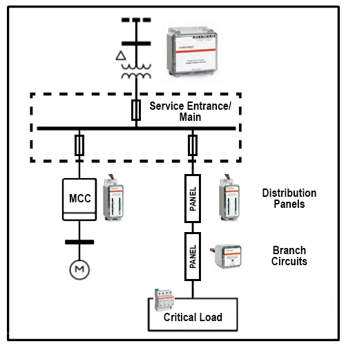
Cascaded Protection Scheme
To maximize system surge protection, system designers and owners often utilize cascaded surge protection. In a cascaded scheme, surge protection devices are utilized in multiple locations throughout the power system. For example, there may be a SPD at the main service entrance, one at each distribution panel or gear, and one at each branch circuit panelboard. Critical equipment may also have SPDs installed on board for additional protection. See Figure below for an example of cascaded protection. Cascading protection has the added benefit of quickly reducing switching surges produced within the facility and preventing them from affecting other equipment.
-
Product Selection and Installation
Installation – Internal vs. External SPD
Since surges are fast transient events, the response of the circuit is different than that of the nominal AC voltage at 50 or 60Hz. The rapid change in voltage appears to the circuit as a high frequency signal and at higher frequencies AC circuits have more impedance. The equivalent frequency of the UL combination wave voltage is 208.3kHz. The main cause of this frequency response is the inductance of the circuit. Simply adding more wire to a circuit adds more inductance and thus higher impedance to the high frequency surge event. Longer lead lengths of SPDs will increase the clamping voltage and reduce their performance in protecting downstream loads. Standard UL VPR testing is performed with 6 inches of lead length. For most applications, this wire lead length is not practical for field installation.
Best Practice in installation is to use the shortest leads possible. Where short leads are not practical, twisting the wire leads will help reduce inductance of the leads and thus reduce the voltage drop and loss of performance. The photo below shows and example of twisted wire leads. See Mersen Tech Topic TT-SPN 8 for more information.
-
Resources
- Surge-Trap® UL/CSA Surge Protective Devices Brochure (PDF, 4181Ko)
- Mersen Surge-Trap SPD Quick Application Guide flyer (PDF, 412Ko)
- Mersen Surge Panel Mount and DIN Rail Cross Reference chart (PDF, 373Ko)
- Surge Protection Note 1: Introduction to Specifying Surge Protection (PDF, 97Ko)
- Surge Protection Note 2: Surge-Trap and the Different kA Ratings (PDF, 177Ko)
- Surge Protection Note 3: TPMOV Construction and Operation (PDF, 333Ko)
- Surge Protection Note 4: Selecting Surge Protective Devices for Electrical Systems with High Resistance Grounding (PDF, 855Ko)
- Surge Protection Note 5: Industrial Machinery and Surge Protective Devices (PDF, 186Ko)
- Surge Protection Note 6: UL 1449 4th Edition Location and/or Type Designations (PDF, 255Ko)
- Surge Protection Note 7: Surge Protective Device Performance and Cascaded Protection (PDF, 283Ko)
- Surge Protection Note 8: Effects of Wire Lead Length on Voltage Protection Rating (PDF, 747Ko)


